Encoders
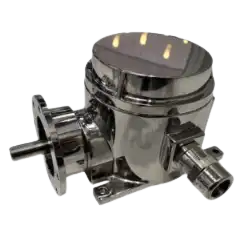
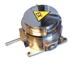
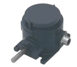
Pitch-Control Limit Switch -
The pitch control system is used to vary the angle of the rotor blades into or out of the wind. By changing the pitch of the blades, the speed of rotation and the power generated can be adjusted. When the power output reaches a critical value, the blade angle mechanism turns the rotor blades slightly out of the wind. As soon as the wind drops again, the blades are turned back again. The setting of the blade pitch has a great influence on the efficiency of the wind turbine.
The rotary limit switches are used to limit the end positions of the blade pitch, set pre-warning points and give precise position signals. These real-time position signals of the blade pitch enable the entire system to optimize the power output.
High-resolution encoders mounted directly in the switch are used for this purpose. Depending on the specification, different BUS systems can be covered.
The gear limit switch thus enables the combination of various safety-relevant tasks in just one application. This is also associated with savings in terms of costs and space requirements.
By using only one B-COMMAND rotary limit switch per leaf, all devices previously used for position monitoring can be saved (e.g. proximity switches and all mechanical devices required for this, i.e. limit switches and encoders on the motors).
By changing the blade angle of the wind turbine, the rotation speed and thus the generated power can be significantly influenced.
The main purpose of the gear limit switches is to generate an exact position signal of the blade position. The basis for an exact adjustment of the blade angle is the possibility to determine the instantaneous position with high precision.
Description Rotor Encoder -
Approvals ➤ INERIS-/ATEX-Certificate: 13ATEX0020X/INE
13.0051X
➤ Mining Class: I M2 d I Mb (ATEX); Ex d I Mb
(IECEx)
➤ Gas and dust classes: 1I2GD Ex d IIB o. IIC T6
Gb Ex tb IIC T85C Db IP66
Specification ➤ Protection degree IP66
➤ Operating temperature -40°C ... +60°℃
➤ G20 Cast iron or stainless steel
➤ Ratio 1:15 ... 1:1578
Yaw-Control limit switch -
To achieve maximum efficiency from wind turbines, it is necessary to keep the position of the rotor perpendicular to the wind. Yawing (controlling the yaw axis / yaw) of the turbine against the wind reduces the fatigue load and ensures longer durability of all components.
They are usually connected via a measuring pinion either directly to the yaw sprocket or connected to the drive pinion of a yaw motor. Gear limit switches fulfil two safety-relevant functions here:
The switch provides two general functions for yaw axis control:
Cable twist sensor (cable twist switch):
The cables connecting the nacelle to the ground components must be secured against twisting. If the turbine is turned in the same direction for a long time, the risk of twisting of the cables increases. The switch measures the twists and limits the end positions for each direction. This prevents twisting and tearing.
Yaw position control / wind tracking
Incremental or absolute encoders and potentiometers can be integrated to detect and continuously monitor the exact nacelle position, with an accuracy of up to 0.001°. The nacelle position signal generated by the limit switch, compared with the wind direction signal from the anemometer, enables the most efficient positioning for the most effective efficiency, i.e. high power output from the wind turbine.
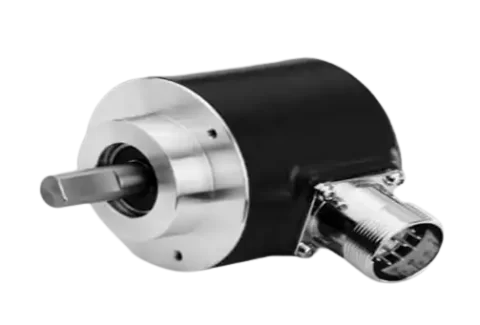
Description Rotor Encoder -
➤ Measurement of hub
speed
➤ Incremental encoder
➤ Resolution 512 pulses
➤ Supply voltage 24VDC
➤ Output signals
A, B, N, A/, B/, N/
Descirption Rotor Encoder
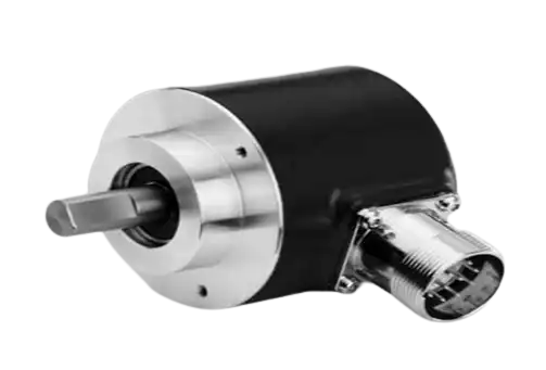
Descirption Rotor Encoder
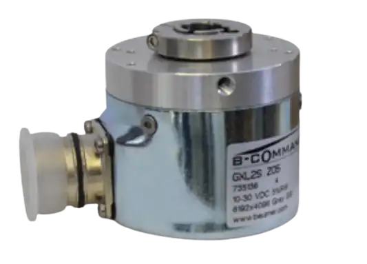
Increamental Encoder
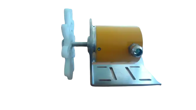
Yaw Encoder
Get connected with us by filling out this form 🤝
We would love to hear from you!
